Sep 14, 2026CNC Machining Guides
Build-to-Print Manufacturing: What Engineers Should Define Before Sending Drawings to a Supplier
Learn what drawings, CAD files, materials, tolerances, finishes and inspection requirements to include in a build-to-print RFQ package.
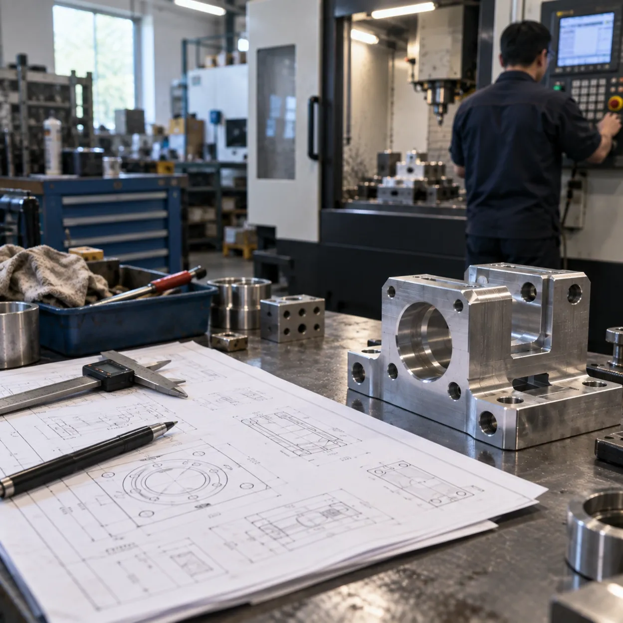
Before sending a build-to-print package to a manufacturing supplier, engineers should clearly define the material grade and condition, critical dimensions and fits, surface finish and secondary processes, inspection requirements, file revisions and quantities.
These requirements give the supplier a documented basis for quotation, manufacturing planning and inspection. A complete 3D model alone may not communicate every requirement that applies to the finished component.
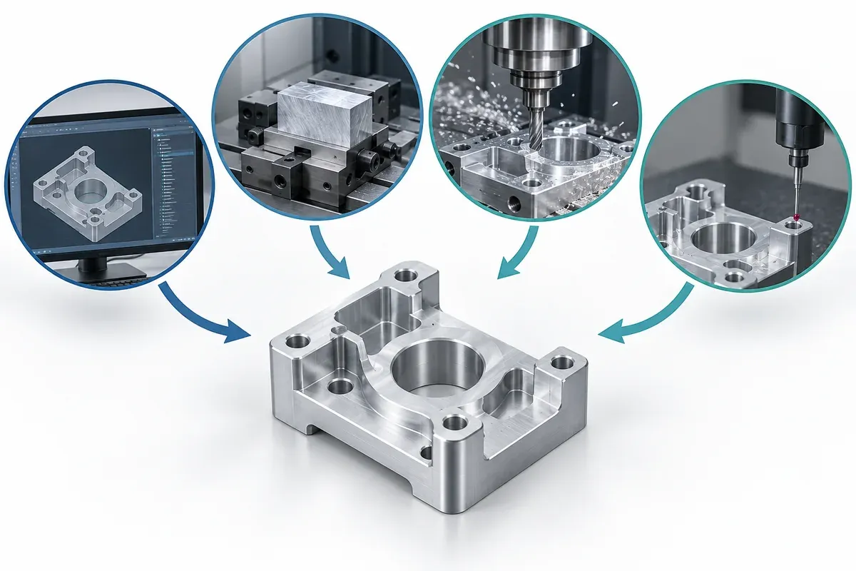
This guide explains what to include in a build-to-print drawing package, how build-to-print differs from build-to-spec, and what to check before releasing files for quotation.
What Is Build-to-Print Manufacturing?
Build-to-print is a manufacturing arrangement in which parts are produced according to customer-controlled drawings, CAD files and specifications.
The supplier’s role typically includes reviewing the manufacturing requirements, sourcing the specified material, planning production, manufacturing the parts and inspecting them against the agreed documentation.
Design authority remains with the customer. A supplier may identify unclear requirements or suggest manufacturing changes, but changes to the released design require customer approval.
This approach can apply to a single replacement component, a prototype, a small batch or multiple drawing numbers belonging to the same equipment project.
Build-to-Print vs. Build-to-Spec
The main distinction is how design responsibility is assigned.
Consideration | Build-to-Print | Build-to-Spec |
|---|---|---|
Customer input | Released drawings, CAD files and manufacturing specifications | Functional, performance and other project requirements |
Supplier responsibility | Manufacture to the customer-controlled design | May include developing a design that meets the requirements |
Design decisions | Controlled and approved by the customer | Assigned according to the agreed project scope |
Acceptance basis | Agreed drawings and manufacturing specifications | Agreed specifications, performance criteria and validation requirements |
For example, a completed fixture-component drawing sent to a machine shop is a typical build-to-print project.
A request to develop a component that performs a specified function involves additional design work. That responsibility should be established before quotation.
Define the Manufacturing Requirements
A complete CAD model does not necessarily contain every requirement needed to quote, manufacture and inspect the finished part.
Check that the drawing, model and accompanying specifications address the following areas.
Material and Condition
Specify the material grade and the condition required for the finished component.
A broad description such as “steel” or “aluminum” may leave important requirements unresolved. Include the alloy, temper, pre-hardened condition or other applicable specification.
Where heat treatment is required, define the finished condition and hardness. Include any processing sequence specifically required by the design so it can be considered during manufacturing review.
Critical Dimensions and Fits
Identify the features that control assembly or function, including:
- bearing seats and bushing fits;
- shaft diameters and bores;
- locating features and shoulders;
- mounting-hole positions;
- mating and sealing surfaces;
- alignment, runout and positional requirements;
- critical thicknesses and installation clearances.
Provide the applicable general tolerances and identify features requiring tighter control. Functional requirements should be clear enough for the supplier to plan both manufacturing and inspection.
For bent brackets, define critical mounting dimensions in the formed condition, including any requirements that apply after finishing. See our custom sheet metal brackets page for manufacturing review and quotation.
Surface Finish and Secondary Processes
State the required surface condition and any secondary processes.
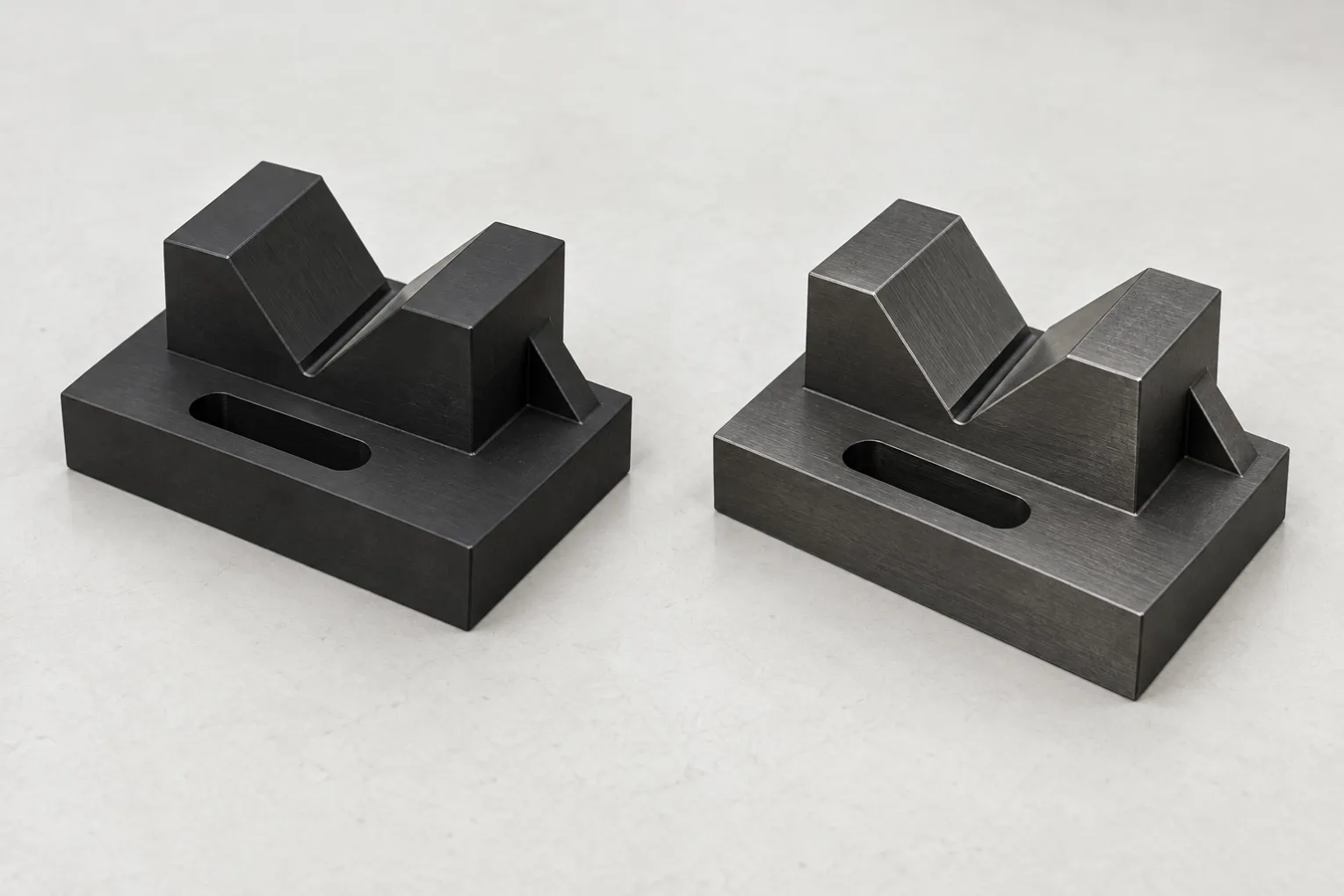
Depending on the component, these may include deburring, grinding, anodizing, black oxide, plating or polishing. Identify which requirements apply to each part and any surfaces requiring special treatment or exclusion.
For a project containing several drawing numbers, avoid leaving the supplier to infer that one finishing requirement applies to every component.
Define Edge Limits and Restrictions After Treatment
“Deburr all edges” should not leave the permitted edge geometry open to interpretation. If a controlled radius or chamfer is required, show its limits and the edges to which it applies. Do not treat a specified radius as permission to add a larger chamfer. Keep mating dimensions and other drawing-defined features within their requirements.
Identify any additional burr restrictions at mating surfaces, hole openings and corners. A requirement for edges that will not scratch during handling does not replace a dimensioned edge limit; both requirements may apply. Agree how conformity will be checked where the drawing does not already define it.
Processing restrictions also belong in the quotation package. For example, a project may require all deburring and cleaning to be completed before nitriding, with no grinding or filing permitted afterward. The supplier needs to assess the part against that sequence, rather than assume that edges can be corrected after treatment. If a proposed manufacturing route cannot meet these restrictions, resolve the issue with the customer before production.
Include the edge callouts and processing notes with the approved drawing and CAD files when requesting a quote. A model showing the final shape may not communicate these restrictions.
Inspection and Documentation
Define inspection requirements during the RFQ stage.
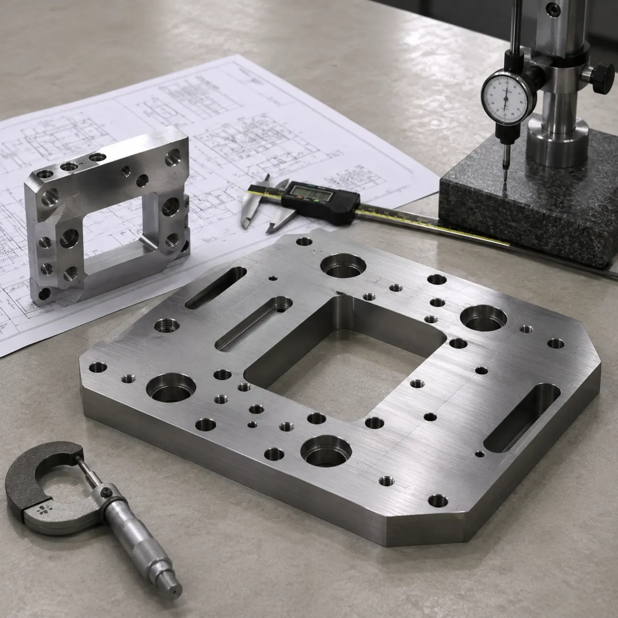
Identify critical characteristics, any specified inspection methods and the reports or certificates required with delivery.
For YSBK orders, dimensional reports, hardness reports and material certificates can be provided when requested and confirmed in the quotation. The testing and documentation scope affects pricing.
A general request for a “quality report” may not communicate the intended scope. State which dimensions, material records or hardness results you need.
Keep Drawings, CAD Files and Revisions Aligned
The supplier should be able to identify the current manufacturing release without choosing between conflicting files.
A 3D model communicates geometry, while a drawing or accompanying specification may define requirements such as tolerances, threads, material condition, finishing and inspection.
Before sending the package, confirm that:
- each component has a clear part number;
- drawing and CAD revisions correspond;
- model geometry and drawing dimensions are consistent;
- notes and specifications apply to the current design;
- obsolete files are clearly separated from the current release;
- quantities are assigned to the correct part numbers.
If the drawing and model disagree, resolve the conflict or provide clear instructions before production.
For repeat orders, confirm the applicable revision. If the design changes, provide the updated approved files so the new requirements can be reviewed.
Using Old Drawings for Replacement Machine Parts
An old drawing may not represent the machine’s current configuration. Repairs, modifications or component changes can affect the dimensions needed for a replacement.
Before releasing an old drawing, have your engineering team confirm the relevant fits, mounting positions, mating features and material requirements against the existing assembly.
A worn component also requires care: its measured dimensions may differ from the intended design dimensions. Copying a worn shaft diameter or damaged locating surface into a drawing can carry the same problem into the new part.
If only an existing component is available, your engineering team or a reverse-engineering provider needs to establish and approve the manufacturing documentation first.
YSBK does not accept physical samples or worn parts for measurement and does not provide drawing reconstruction. We review customer-approved documentation for manufacturing.
For one-off and low-volume components made to confirmed drawings, see our Custom Replacement Machine Parts page.
Build-to-Print RFQ Checklist
Use the checklist below to assemble the quotation package.
Information | What to Provide |
|---|---|
Part identification | Part number and description for each component |
Drawing | Current approved drawing and revision |
CAD files | STEP/STP or other agreed model format, with the applicable revision |
Material | Grade and required material condition |
Quantity | Quantity for each part number and expected repeat demand, if known |
Tolerances | General tolerances and identified critical fits or dimensions |
Heat treatment | Required treatment, finished condition or hardness |
Surface requirements | Finish, coating and applicable secondary processes |
Inspection | Critical characteristics, reports and certificates required |
Delivery | Required delivery date or project schedule |
For multiple components, include a parts list or BOM linking each part number to its quantity and revision.
If a requirement is still unresolved, identify it clearly in the RFQ. The supplier can then distinguish confirmed requirements from items awaiting customer approval.
Ready to Send Your Drawings for a Quote?
YSBK Parts manufactures drawing-defined CNC components for prototypes, one-off parts, low-volume equipment projects and repeat orders.
Send your approved drawings and available CAD/STEP files with the material, quantities, critical requirements and required timing. Include any inspection reports or certificates needed so they can be considered in the quotation.