Sep 16, 2026CNC Machining Guides
2D Drawing vs 3D CAD for a CNC Prototype Quote
Learn when a STEP file is enough for a prototype quote, what a 2D drawing must define, and why complex CNC parts often require both files.
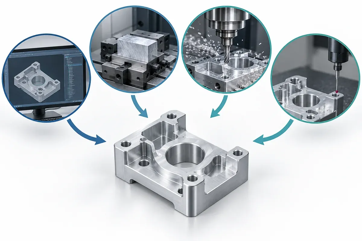
Many prototype enquiries begin with a STEP file. It is usually enough for a supplier to see the overall shape, identify the main machining features and prepare an initial estimate.
The situation changes when a part has critical fits, angled holes, internal features or specific inspection requirements. The 3D model shows the geometry, but it may not show which dimensions control the assembly, how tight the tolerances must be, or what surface finish is required.
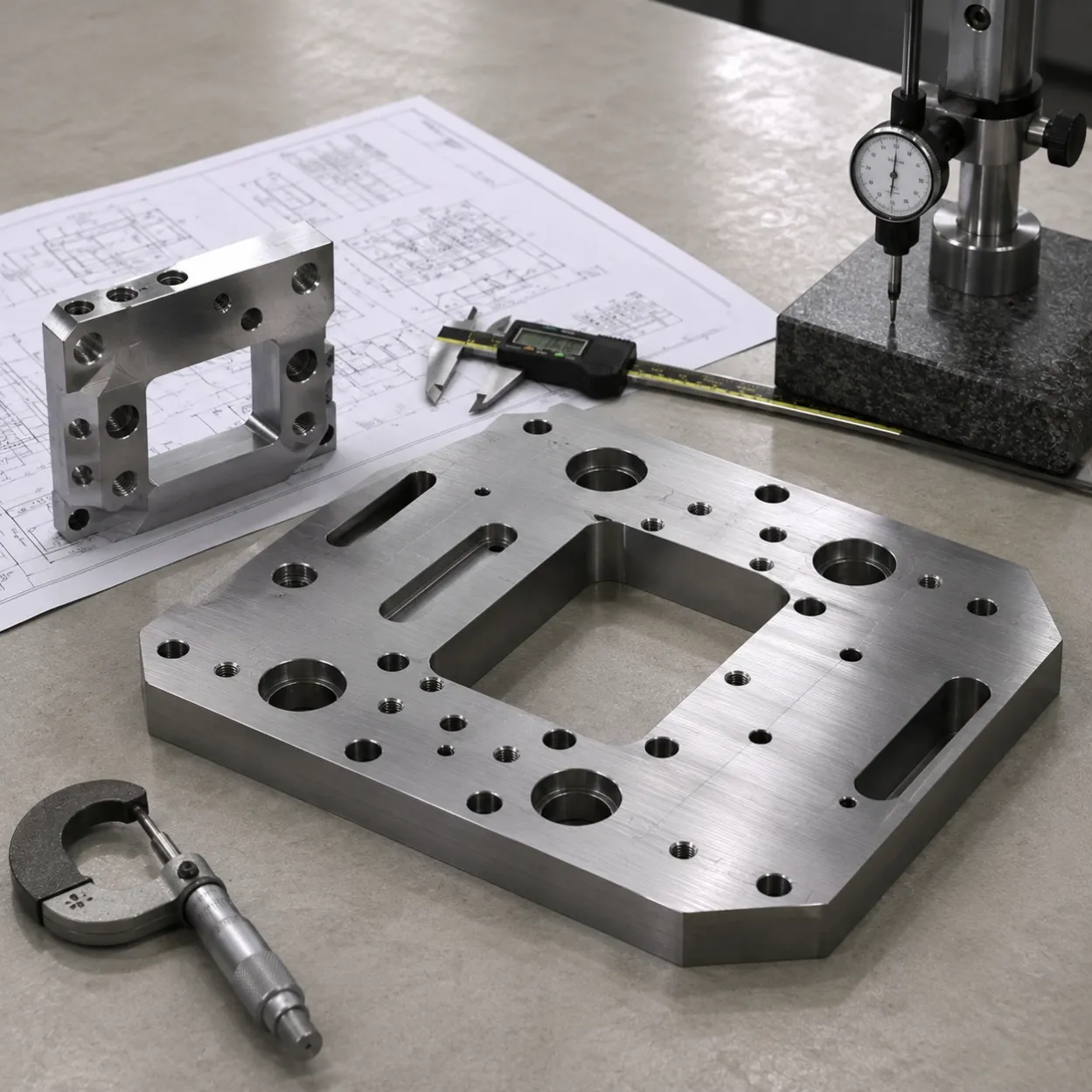
For a more reliable CNC prototype quote, send both the 3D CAD model and the 2D drawing when they are available. Each file answers a different set of manufacturing questions.
If only one file is ready, it can still be reviewed. The important point is to make clear what information is missing and what the prototype needs to verify.
Is a STEP File Enough for an Initial Quote?
For many early enquiries, yes.
Product designers often send a STEP file first because they want to check whether the part can be manufactured and obtain an approximate cost before completing the full drawing package. The model allows an engineer to review:
- the overall geometry;
- approximate part size and stock requirement;
- pockets, holes and other visible features;
- likely machining operations;
- basic tool access;
- and obvious thin-wall or deep-feature risks.
For a simple part with standard tolerances, the STEP file may provide enough information for an initial estimate. It should not automatically be treated as the complete manufacturing specification.
A 3D model normally does not tell the supplier which dimensions are critical, whether a hole is a close fit, what surface roughness is required, or which features must be included in an inspection report. These details can change the machining and inspection plan.
What Does the 2D Drawing Add?
The 2D drawing records the requirements that cannot be safely assumed from the solid model.
Depending on the part, it may define:
- critical dimensions and tolerances;
- datum references and GD&T requirements;
- threads, counterbores and countersinks;
- material grade;
- surface roughness;
- anodizing, blasting, polishing or other finishing requirements;
- inspection points and report requirements;
- and drawing revision or unit information.
This matters most when the prototype will be used for assembly or functional testing. A model may show that two features exist, while the drawing explains how accurately they must relate to each other.
When only a 2D drawing is available, a simple component may still be reviewed. For a part with complex spatial features, however, engineers may need additional views or may need to reconstruct a 3D model before the machining approach can be assessed properly. That adds clarification work and can extend the quoting process.
When a 2D Drawing Did Not Show the Full Machining Difficulty
We once received a prototype enquiry with only a 2D drawing available. Based on the information provided, the part could be reviewed and an initial quote prepared.
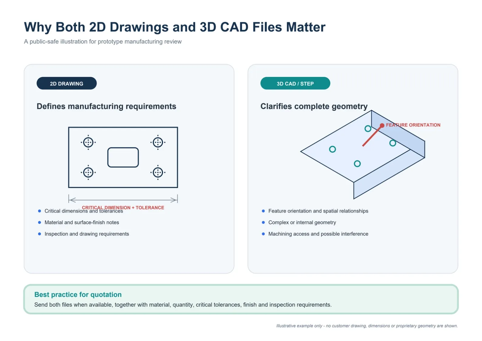
After the PO was placed, the customer provided the 3D STEP model. During the engineering review, the model made the orientation of an angled hole much clearer. The feature was more difficult to locate and machine than the 2D views had suggested.
The issue was not simply the hole diameter. Its position and angle affected tool access, part positioning and workholding. The manufacturing team needed additional clarification before machining could begin.
If the STEP file had been available during the quoting stage, that difficulty could have been identified earlier and considered more accurately in the process plan and quote.
This example does not mean that the 3D model replaces the drawing. The two files answered different questions:
- the 3D model clarified the feature orientation and overall geometry;
- the 2D drawing carried the tolerance, material, finish and inspection requirements.
Providing both files during the quoting stage helps reduce later questions about process planning, pricing and delivery expectations.
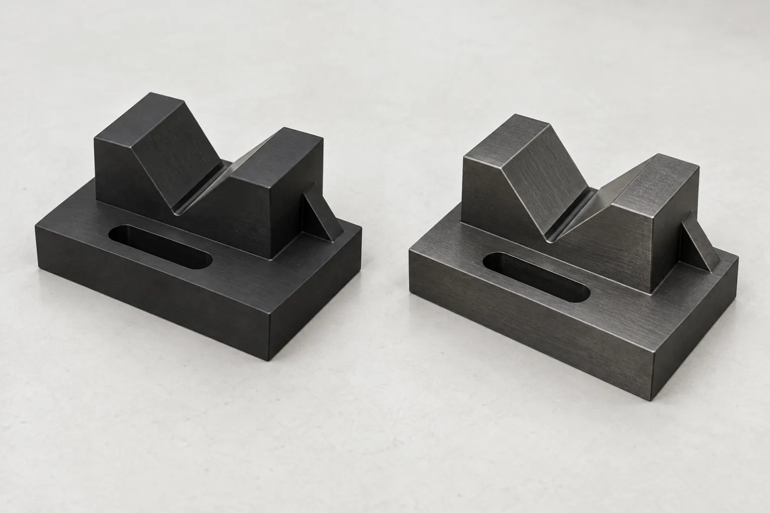
Illustrative example only. No customer drawing, dimensions or proprietary geometry are shown.
What Information Is Most Often Missing From a Prototype RFQ?
The file format is only part of the quotation. Three other gaps regularly lead to follow-up questions.
Material grade and substitution permission
“Aluminum,” “steel” or “plastic” is not enough to select material and prepare a reliable quote. The request should state the required grade, such as 6061 aluminum, 7075 aluminum, 316 stainless steel, ABS, POM or PEEK.
If an alternative material is acceptable for the first prototype, say so. If the final production material is required for functional testing, make that clear as well.
Critical tolerances and surface finish
A STEP file contains nominal geometry. It does not identify which dimensions must be held tightly or which surfaces affect assembly.
Mark the dimensions, fits and datum relationships that matter to the test. Also specify whether the part needs anodizing, sandblasting, polishing, coating or another finish. Appearance requirements and functional finish requirements should not be left to assumption.
Prototype purpose and quantity
The same geometry may require a different manufacturing approach depending on whether the part is for:
- assembly verification;
- functional or load testing;
- motion testing;
- thermal or wear testing;
- or appearance review.
Quantity matters too. Most prototype enquiries received by YSBK are for one piece, two pieces or three to five pieces. Some design iterations require 10 to 20 pieces. When demand moves beyond approximately 50 pieces, it may be useful to compare low-volume CNC machining with another process, depending on the material, geometry and required consistency.
What Does YSBK Check Before Confirming the Manufacturing Requirements?
When files are submitted for a prototype or low-volume project, the engineering review may include:
- File condition and consistency - checking whether the STEP model opens correctly, whether it contains a usable solid body, and whether the 2D and 3D files agree in revision, units and dimensions.
- Manufacturability - reviewing thin walls, deep holes, internal corners, undercuts, difficult setups and features that may be hard to reach.
- Deformation risk - considering how the selected material and part structure may behave during machining.
- Tolerance requirements - identifying critical tolerances and checking whether they are reasonable for the geometry and proposed process.
- Feature details - reviewing threads, counterbores, countersinks, chamfers, datum references, GD&T and surface-roughness notes.
- Finishing and inspection - confirming material, surface treatment, required measurement records and any specified CMM inspection.
- Delivery information - confirming quantity, requested timing, packaging and confidentiality requirements.
An unclear or conflicting requirement should be confirmed with the customer before it becomes part of the manufacturing plan. The purpose of this review is not to change the design without approval. It is to make sure the supplier and customer are working from the same requirements.
Which Prototype Parts Usually Need Both Files?
Using both files is particularly useful for:
- mounting bases and equipment brackets with related hole positions;
- motor mounts and automation components;
- housings and cavities with internal features;
- shafts, bushings, sliders and locating components;
- parts with angled or intersecting holes;
- components with tight assembly fits;
- and prototypes that require a dimensional inspection report.
YSBK commonly reviews prototype and low-volume enquiries for aluminum parts, stainless-steel parts and engineering-plastic parts. Frequently requested materials include 6061 and 7075 aluminum, 304 and 316 stainless steel, ABS, PC, POM, nylon and PEEK. Final suitability depends on the drawing, intended test and individual part geometry.
You can also review our prototype CNC machining service or learn more about CNC machining services for custom parts manufactured from drawings.
What Should You Send for a CNC Prototype Quote?
Send the information you already have. When possible, include:
- the 3D CAD or STEP model;
- the 2D PDF drawing;
- material grade and whether substitution is permitted;
- quantity;
- prototype purpose;
- critical dimensions and tolerances;
- surface-finish requirements;
- inspection or documentation requirements;
- and the requested delivery date.
If only the STEP file is ready, identify the critical features and explain what the prototype needs to prove. If only the 2D drawing is available, note whether a 3D model can be provided before the requirements are finalized.
Frequently Asked Questions
Can I request a prototype quote with only a STEP file?
Yes. A STEP file can often support an initial estimate, especially for a simple part. Material, quantity, critical tolerances, finish and inspection requirements may still need to be confirmed before the final manufacturing requirements are agreed.
Is a 2D drawing required for every CNC prototype?
Not every early prototype needs a complete drawing package. A 2D drawing becomes more important when the part has critical fits, threads, GD&T, surface-roughness requirements, finishing notes or defined inspection criteria.
What if my 2D drawing and 3D model do not match?
Confirm which file and revision takes precedence before manufacturing. Suppliers cannot safely assume which version controls the part. Highlight the updated feature and issue matching files whenever possible.
Why does an angled hole affect the quote?
An angled hole may require a different setup, special positioning, additional workholding or a separate machining operation. Its difficulty depends on the angle, depth, access and relationship to other features, not only its diameter.
Send the Files Before the Quoting Stage Is Closed
If both files are available, submit the 2D drawing and 3D CAD or STEP model together. This gives the engineering team a clearer view of both the geometry and the manufacturing requirements before pricing and process planning are finalized.
If your files are ready, contact YSBK and submit your prototype RFQ with the material, quantity, critical tolerances, surface finish and inspection requirements.